
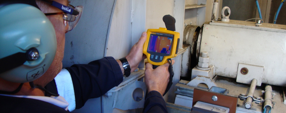
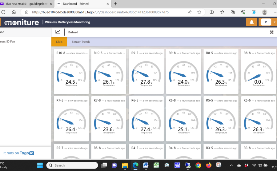
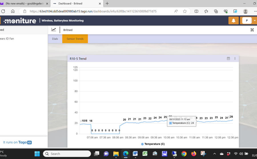
24/7 Online induction self powered heat sensors:
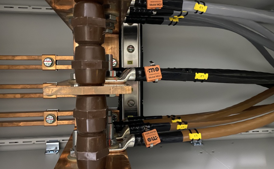
Cables to Bus bars.
The inside of a bus bar chamber with the heat sensors monitoring the temperature rise and falls of the cabling and bus bars.
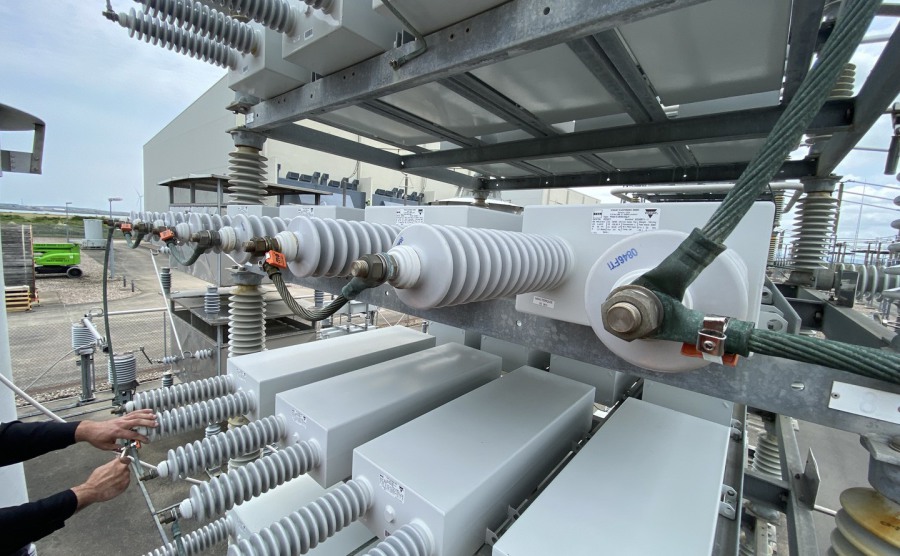
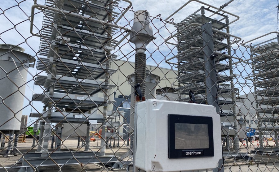
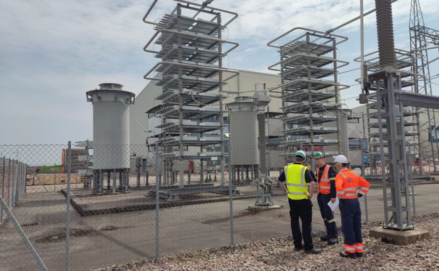
400Kv Capacitors.
The heat sensors have been installed onto the cable into each capacitor looking for a spike in temperature due to high resistance as the capacitor fails.
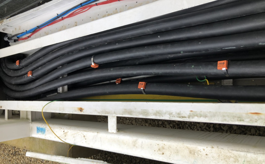
Duct cabling.
Heat sensors fitted to cabling within the duct system to monitor any abnormal rise in temperatures.
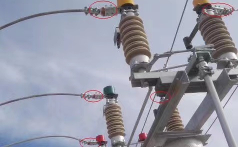
HV Cable.
Heat sensors fitted to the overhead HV cables at termination points where there may be a build up of temperature due issues such as PD, tracking & arcing.
 Print
Print 